Predicting coating composition, deposition rate and hysteresis in a reactive PVD process
The Partners
This case study is one of examples of mutual productive co-operation of PlasmaSolve with the Belgian company Innovative Coating Solutions (ICS). ICS is a company that develops custom processes and assists industry leaders in integrating these processes into their coating equipment. To do so, ICS is operating several PVD and PECVD coaters.
The project presented mutual benefit – ICS gained deeper understanding of their drum coater (coating uniformity, variations in coating composition) while PlasmaSolve obtained high-quality validation data for their MatSight model of reactive sputtering.
Problem Specification
The project had the following goals on the ICS and PlasmaSolve side:
Predict atomic composition of a nitride coating prepared by reactive magnetron sputtering using PlasmaSolve’s MatSight software
Validate the accuracy of spatially-resolved deposition rate predictions from PlasmaSolve’s MatSight software
Confirm whether MatSight predicts the correct hysteresis curve of the reactive sputtering process.
Proof-of-concept coupling of PlasmaSolve’s MatSIght to ICS’s Virtual Coater software and perform a combined simulation of plasma process as well as film growth
All these goals were ultimately reached and the results are a good demonstration of both PlasmaSolve’s and ICS’s joint capabilities.
Coater specification
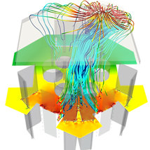
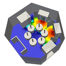
The coating chamber – a drum coater – consists of two planar targets (red colour) connected to DC power supplies (2.2 kW at each target). Both targets are made of titanium/aluminium alloy in the ratio of 1:1. The process gas (argon and nitrogen) is fed into the chamber via 4 showerheads (orange), located along side each target.
The vacuum pump (purple) is located on top of the chamber, separated from the coating zone by a top plate. The silicon substrates were placed all over two (out of total six) dummy cylinders (various colours on the orange and purple cylinder).
Model performance in terms of coating composition – left part shows 8 training experiments, right part shows 4 validation experiments.
Simulation Strategy
The MatSight Reactive Sputtering App is actually a self-consistent model coupling 3 distinct physics sub-models
gas flow (3D, particle based DSMC method),
metal sputtering and transport (3D, DSMC),
global plasma model (solved for each cathode separately).
Each of these models has a different characteristic time scale. To reach a physically meaningful and self-consistent solutions, the three sub-models have to be coupled in a rather ingenious manner.
3D Gas flow model
The simulation describes reactive gas flow in the coater – the gases (Argon, Nitrogen) are injected at the inlet, pumped by the pump but additionally, nitrogen can be consumed at the targets, substrates and chamber walls. The consumption rate of Nitrogen does, however, depend on the 3D-spatially resolved flux of deposited metal vapors …
3D sputtering model
… the distribution and deposition of metal vapors is described by a different particle based model, which solves the partially ballistic, partially diffusive transport of metal atoms between the target and the rest of the coater. In this simulation, the sputtering yield of each metal depends on the state of poisoning of each target …
Plasma model
… and the poisoning or de-posioning of each target in the coater (note that each coater is posioned differently) is addressed by global plasma models. The global plasma models need inputs especially from 3D gas flow (instantaneous nitrogen pressure), which closes the coupling loop.
Hysteresis curve prediction
First verification measure for a reactive sputtering simulation is the hysteresis curve. The hysteresis curve is a characteristic “fingerprint” of each process and if the model reproduces it, it is most likely correct.
Our model is complex enough to distinguish between the metallic and poisoned branches. As in real process, this only depends on the initial conditions: if we start with no nitrogen in the chamber, we end up in the metallic part, if we fill the chamber with nitrogen we simulate the poisoned part.
In the chart, each simulated point corresponds to a 3D ab-initio simulation. We are happy to report that the simulated hysteresis curve is very close to the experimental one.
Simulating the coating composition
The ultimate verification of the model is the coating itself. Therefore, we distributed 9 probe samples over the dummy cylinders in the drum coater. The samples were always a pair consisting of a silicon coupon and a quartz crystal microbalance. That way, the coating composition and coating deposition rate can be measured simultaneously.
The rotation of the table was deliberately turned off for the purposes of the validation (one of the cylinders was directly facing a target, second was sideways) and a standard TiAlN deposition process was executed.
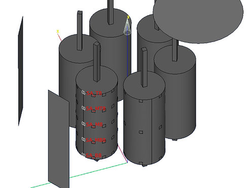
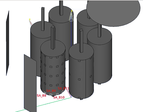
The probe samples are designated by a consistent naming convention, see the figures below
All the samples that were placed on the cylinder in front of one of the targets were prefixed with “SA_” (samples on the other cylinder were prefixed with “SB_”).
These samples were placed in five horizontal rows, marked with letters T (top row), MT (mid-top), M (middle), MB (mid-bottom), and B (bottom).
Finally, each sample was also marked with a number corresponding to a column in which it was placed (number 8 marks column facing centre of the target).
As the figure below illustrates, the deposition rate predicted by the model matches almost exactly the measured one on all the probe samples and the variation in deposition rate between individual samples (i.e. different positions in the coater) is captured very well. What is even more remarkable is the quantitative accuracy – the mass deposition rate matches the experiment without the need to introduce a fitting constant or a scaling factor. This confirms that MatSight’s internal sputtering yield database of sputtering yields is accurate for TiAlN.
The atomic composition of the coating is also captured accurately and the model even captured Aluminum under-stroichiometry on sample SA-M6 and SB-M3. The model only starts to deviate from the experimental measurement at probe samples with very low coating thickness – this can be improved by increasing the number of simulation particles in the model.
Measured (blue bars) and simulated (red+orange bars) absolute deposition rate of TiAlN. The mass deposition rate relates to thickness deposition rate through coating density. The percentage at each bar designates the atomic content of Al in the coating obtained from the model. For two samples, XPS measured composition was measured.
We did a step further and performed atomistic scale simulations of the film growth using the kinetic Monte-Carlo simulation tool NASCAM™ (NanoSCale Modeling) of the software Virtual Coater™ developed by UNamur and sold by Innovative Coating Solutions (ICS). Such simulations were done according to velocity distribution function computed from the MatSight sputtering simulation at individual samples’ locations. We were able to identify such properties as film thickness or columns angle.
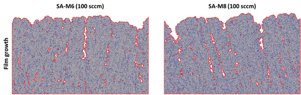
Kinetic Monte-Carlo simulation of film growth on two probe samples compared with SEM cross-sections of the coating.
Film growth simulation with NASCAM™
We did a step further and performed atomistic scale simulations of the film growth using the kinetic Monte-Carlo simulation tool NASCAM™ (NanoSCale Modeling) of the software Virtual Coater™ developed by UNamur and sold by Innovative Coating Solutions (ICS). Such simulations were done according to velocity distribution function computed from the MatSight sputtering simulation at individual samples’ locations. We were able to identify such properties as film thickness or columns angle.
Moreover, we were able to predict coating properties as the chemical composition, the effective thermal conductivity or the porosity (pores occluded or connected to the surface).
These simulation results were benchmarked with experimental ones like relative thickness or deposition rate (profilometry), chemical composition (XPS), surface and cross section morphology (SEM) and porosity (SEM).
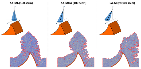
This study were extended to more complex objects: namely the sharp edge of cutting tools. It allowed us to highlight the influence on the coating quality of the position and the orientation of the object in the coating chamber.
PlasmaSolve
PlasmaSolve is a team of subject matter experts in plasma-powered technologies and materials science. Our mission is to create reliable and faithful digital twin models for these cutting-edge technologies. We achieve this by synergizing physics simulation, chemistry simulation, machine learning, data mining, and material characterization.
At PlasmaSolve, we specialize in helping businesses improve their PVD, PECVD, and ion source equipment. We have extensive experience in developing new processes and retrofitting existing equipment to meet evolving industry needs. Our team’s expertise also extends to simulation-guided design of other plasma sources, such as gas conversion reactors or satellite electric propulsion systems.
MatSight
PlasmaSolve started as a consultancy company that specializes in plasma-powered technologies and materials science. As of 2023, we are expanding our services to include the development of highly specialized plasma simulation software called MatSight. The first cohort of PlasmaSolve’s MatSight Apps have already been delivered to early-adopter companies and you will soon be hearing more about this innovative software tool..
Applied Research Grants
Although public co-funding comprises only a minor portion of our annual turnover, it is a vital resource stream that helps us develop new, cutting-edge simulation tools for PVD, PECVD, and ion sources.
IraSME FastPIMS (2023-2025)
Partners: Fraunhofer IWM, Aurion GmbH
Project “FastPIMS: Simulation driven Fast switch match system for pulsed rf/HiPIMS plasma applications”, reg.no. CZ.01.01.01/01/22_002/0000106 is co-funded by the European Union. The aim of the project is to develop a global RF and HiPIMS sputtering model that will allow the sputtering process of oxide coatings to be configured and customised for specific users and their applications without the need for a lengthy testing process.
TAČR OPTIMISM (2020-2025)
Partners: Masaryk University, SHM s.r.o.
Scope: PlasmaSolve is coordinating this research project, where we are implementing computationally efficient coater-scale plasma models and demonstrating their efficiency on ta-C and AlCrN coatings grown by high-power magnetron sputtering. Another important aspect of the project is absolute measurement of sputtering yields in various contexts (metalic, poisoned, …)
TAČR SILAS (2023-2025)
Partners: SpaceLabEU SE (coordinator), Brno University of Technology
Scope: PlasmaSolve is developing a digital twin model for a unique ECR ion source. The key characteristic of the ECR ion source is the ability to operate at very low pressures, as low as 20 mPa. The primary application of the device is air-breathing satellite electric propulsion but a laboratory version of the device is also envisioned.
M-era.net MIST (2020-2021)
Partners: Université de Namur (coordinator), AGC Plasma
Scope: The project coordinated by UNamur aimed to create a Multi-scale simulation toolbox for PECVD processes. The efficiency and accuracy of the simulation toolbox combining PlasmaSolve’s and UNamur’s models was illustrated on the example of the AGC’s novel hollow cathode technology.
Horizon 2020 PlasmaJetPack (2019-2022)
Partners: COMAT (coordinator), OHB Sweden, CNRS Icare, Bundeswehr Uni München CNRS Laplace, TAS France
Scope: COMAT is a developer of a disruptive solid-propellant vacuum arc thruster for satellites. PlasmaSolve contributed to their ambitious goal by numerical modeling of the vacuum arc and its contraction under magnetic fields. In the process, PlasmaSolve has significantly improved its vacuum arc simulation capabilities and created a trustworthy database of vacuum arc erosion rates for various cathode materials.
Scientific Papers
As time-consuming as it is, we try to publish our research regularly as a way of paying back to the academic community that we are learning a lot from!
K. Tomanková et al. Simulation of a hollow-cathode PECVD process in O2/TMDSO for silicon dioxide deposition – Cross-code validation of 2D plasma model and global plasma model. Surface Coatings and Technolgy 474 (2023). Open-access.
A. Roštek et al. Simulating ion flux to 3D parts in vacuum arc coating: Investigating effect of part size using novel particle-based model. Surface Coatings and Technolgy 449 (2022)
K. Mrózek et al. Global plasma modeling of a magnetized high-frequency plasma source in low-pressure nitrogen and oxygen for air-breathing electric propulsion applications. Plasma Sources Science and Technology 30 (2021). Open-access.
M. Kubečka et al. Predictive simulation of antenna effect in PVD processes using fluid models. Surface Coatings and Technology 379 (2019).
R. Rudd et al. Plasma gas aggregation cluster source: Influence of gas inlet configuration and total surface area on the heterogeneous aggregation of silicon clusters. Surface Coatings and Technology 364 (2019)
R. Rudd et al. Manipulation of cluster formation through gas-wall boundary conditions in large area cluster sources. Surface Coatings and Technolgy 314 (2016)
What’s next? Get in touch! Try MatSight
A limited amount of trial versions that you can try on-premise is available. Email us to see if you qualify.
If you have any questions or comments, do not hesitate to contact us+420 776 185 170